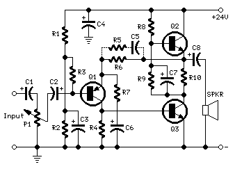
3 - 5 Watt Class-A Audio AmplifierBehaves like a one-valve operated amplifierSimple circuitry - No cross-over distortion Circuit diagram:Parts:P1_____________47K Log. Potentiometer (Dual-gang for stereo)
R1____________100K 1/4W Resistor
R2_____________12K 1/4W Resistor (See Notes)
R3_____________47K 1/4W Resistor
R4______________8K2 1/4W Resistor
R5______________1K5 1/4W Resistor (Optional, see Notes)
R6______________2K7 1/4W Resistor
R7,R9_________100R 1/4W Resistors
R8____________560R 1/2W Resistor (See Notes)
R10_____________1R 1/2W Resistor
C1,C2__________10µF 63V Electrolytic Capacitors
C3_____________47µF 25V Electrolytic Capacitor
C4____________100µF 35V Electrolytic Capacitor
C5____________150nF 63V Polyester Capacitor (Optional, see Notes)
C6,C7_________220µF 25V Electrolytic Capacitors
C8___________1000µF 25V Electrolytic Capacitor
Q1___________BC560C 45V 100mA Low noise High gain PNP Transistor
Q2,Q3________BD439 60V 4A NPN Transistors
SPKR___________One or more speakers wired in series or in parallel
Total resulting impedance: 8 Ohm
Minimum power handling: 5W
Comments:In the old valve days, most commercial audio amplifiers suited for compact integrated mono or stereo record players used a one-valve amplifier topology. The circuit was usually implemented by means of a multiple type valve, e.g. a triode pentode ECL86.
Common features for those amplifiers were: Class A operation, output power in the 3 - 5W range, input sensitivity of about 600mV for full output power, THD of about 3% @ 3W and 1KHz.
Best types showed THD figures of 1.8% @ 3W and 0.8% @ 2W.
This solid-state push-pull single-ended Class A circuit is capable of providing a sound comparable to those valve amplifiers, delivering more output power (6.9W measured across a 8 Ohm loudspeaker cabinet load), less THD, higher input sensitivity and better linearity.
Voltage and current required for this circuit are 24V and 700mA respectively, compared to 250V HT rail and 1A @ 6.3V filament heating for valve-operated amplifiers.
The only penalty for the transistor operated circuit is the necessity of using a rather large heatsink for Q2 and Q3 (compared to the maximum power delivered).
In any case, the amount of heat generated by this circuit can be comparable to that of a one-valve amplifier.
An optional bass-boost facility can be added, by means of R5 and C5.
This circuit was built and compared with a one-valve box gramophone circuit of the late 1950s by
Aren van Waarde, a Dutch biochemist working in the field of medical imaging (PET) with a strong interest in audio and valve amplifiers.
A thorough description of both circuits and the results of subjective test comparisons made by this distinguished Author appeared on
AudioXpress magazine: February, March and April 2005 issues.
Technical data:(measured on 8 Ohm resistive load unless otherwise specified)
Sensitivity:
230mV input for 1.5W output
380mV input for 3.5W output
560mV input for 5.6W output
Sensitivity with bass-boost:
400mV input for 1.5W output
630mV input for 3.5W output
850mV input for 5.6W output
Sensitivity with 8 Ohm nominal, loudspeaker cabinet load:
210mV input for 1.5W output
325mV input for 3.5W output
477mV input for 6.9W output
Frequency response:
100Hz to 20KHz 0dB; -3dB @ 40Hz
Frequency response with bass-boost:
+5dB @ 100Hz; +3.9dB @ 200Hz; +2.5dB @ 400Hz; -1dB @ 10KHz and 20KHz
Total harmonic distortion @ 1KHz:
0.3% @ 0.5W; 0.45% @ 1W; 1% @ 5.6W
Unconditionally stable on capacitive loads
Notes:
- If necessary, R2 can be adjusted to obtain 13V across C8 positive lead and negative ground.
- Total current drawing of the circuit, best measured by inserting the probes of an Avo-meter across the positive output of the power supply and the positive rail input of the amplifier, must be 700mA. Adjust R8 to obtain this value if necessary.
- Q2 and Q3 must be mounted on a finned heatsink of 120x50x25mm. minimum dimensions.
- Add R5 and C5 if the bass-boost facility is required.